Showing posts with label PROJECTS. Show all posts

Monday, 25 November 2013

/*
 * SERVOS_EXECUTION.c
 *
 * Created: 25-Nov-13 11:37:32
 *  Author: avrnarm
 */

#define F_CPU 16000000ul
#include <avr/io.h>
#include <util/delay.h>

int main(void)
{
DDRC=0xFF;
DDRD=0xFF;
char i ;
    while(1)
    {

_delay_ms(2000);
for (i=0;i<2;i++)
{
PORTC=0xFF;
PORTD=0xFF;
_delay_us(1000+5.55*10) ;
PORTC=0x00;
PORTD=0x00;
_delay_us(2010) ;
}

Friday, 15 November 2013

/*
Interfacing Ultra Sonic Module (4 PIN HCSR04) with Atmega16
Hardware Pin Configuration: Vcc, Gnd, Trigger input pulse, echo output pulse.

LCD Connected to port A.
Sensor to PORTD.

Sensor |

Trig   --> PD0
Echo   --> PD1
Vcc   --> Vcc
Gnd   --> Gnd

 Programmer: Raj Prajapati
 rajatmelavr@gmail.com

 For any query

*/

//Header File
#include <avr/io.h>
#include <util/delay.h>
#include "ilcd.h"
//Macros
#define US_PORT PORTD
#define US_PIN PIND
#define US_DDR DDRD
#define US_TRIG PD0
#define US_ECHO PD1
//Globle Variable
int distance;
//Calculating width of high pulse in micro second.
#define US_Time_out -12
#define US_NO_OBSTACLE -13
void US_init();
void US_trig();
void US_init()
{
US_DDR|=(1<<US_TRIG);
}

void US_trig()
{
//Send a 10uS pulse on trigger line

US_PORT|=(1<<US_TRIG); //high

_delay_us(15); //wait 15uS

US_PORT&=~(1<<US_TRIG); //low

Monday, 28 October 2013

AVR: Stopwatch With Interrupt Timer and Multiplexed 7 segment Display

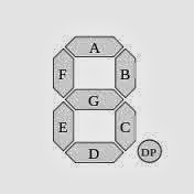
Here we are connecting the 7 segment display with PORTA, i.e. Multiplexing of six-7segment display, with the control lines to PORTB. Following is the program to Interface the 7segments.

Crystal : 8MHz
Time: 0.125uSec
Prescaler: clk/1025
Timer Interrupt : 25mSec.
For 1sec , run this timmer for 40 times.

We can achieve max delay of appx. 35000uSec or 35mSec with 8MHz crystal frequency and prescaler (clk/1024).

Program: 

/*
 * two_7seg.c
 *
 * Created: 27-Oct-13 19:08:04
 *  Author: avrnarm
 */ 

/* PROGRAM to execute the counter with the multiplexed 7 segent display */
#define FUSE_CKSEL0 0
#define FUSE_CKSEL1 0
#define FUSE_CKSEL2 1
#define FUSE_CKSEL3 0

#include<avr/io.h>
#define F_CPU 8000000Ul
#include<util/delay.h>
#include<avr/interrupt.h>

unsigned int j,ss=0,mm=0,hh=0;
char ssd[]={0x3f,0x06,0x5b,0x4f,0x66,0x6d,0x7d,0x07,0x7f,0x6f}; // Hexadecimal values for the 7 Segment display generated by the look up table
char ssd_dec[]={0xbf,0x86,0xdb,0xcf,0xE6,0xEd,0xFd,0x87,0xff,0xEf}; // Hexadecimal values for the 7 Segment display generated by the look up table

int main(void)
{
DDRA=0xFF;
DDRB=0xFF;
//*********************TIMER***(8MHz crystal....clk/1024 prescaler......Obtained 25ms delay
TCNT0=61;
TCCR0=0x05;
TIMSK=(1<<TOIE0);
//*********************
sei();
while(1)
    {
// for seconds
PORTB=0xFF;
PORTA=ssd[(ss)/10];

Friday, 25 October 2013

NotePad Design with Atmega16/32 on 16x2 LCD with UART


Here in this program we are designing the notepad by using Atmega16/32 as a controller and LCD for displaying the typed that we will be sending from the help of  UART. In Proteus, with the help of the Virtual Terminal , we will send the data to the uC and the same data will be displayed on the 16x2 LCD in the same way we type in the Notepad. Once you had written the max 32 character, Lcd will get clear and go back again to home position to provide you the space of the further character you will be sending from the UART.


Hardware Connection : -


***************************PROGRAM*****************************


//Program to interface the LCD, Uart and Keyboard

#include<avr/io.h>
#define F_CPU 1000000ul
#include<util/delay.h>
#include<stdlib.h>

//Flag to moniter no of bit received
char flag=0;


//Setting Fuse Bit

#define FUSE_CKSEL0 0
#define FUSE_CKSEL1 0
#define FUSE_CKSEL2 1
#define FUSE_CKSEL3 0

//**********************************LCD START************************************
/* LCD bit connection

Lcd Interfacing in 8-bit mode
PA0 --> D0
PA1 --> D1
PA2 --> D2
PA3 --> D3
PA4 --> D4
PA5 --> D5
PA6 --> D6
PA7 --> D7

PB0 --> RS
PB1 --> RW
PB2 --> EN

*/

//Macros For Lcd
#define LCD_PORT PORTA
#define rs (1<<0)
#define rw (1<<1)
#define en (1<<2)

KEYPAD...UART (Universal Asynchronous Receiver Transmitter)...AND LCD (Liquid crystal display) Interfacing with Atmaga16/32


Following code will be defining the processing of the UART (checked in Proteus) with baud rate of 1200 bits/second with internal crystal of the ATmega16.


Here we are connecting the Keypad in the PORTC of the uC , LCD on the PORTB and the Virtual terminal in the Proteus to summarize the  exact working of the Uart.

 We had connected 4x3 LCD Matrix. 


//Program to interface the LCD, Uart and Keyboard


#include<avr/io.h>

#define F_CPU 1000000ul
#include<util/delay.h>
#include<stdlib.h>

//Setting Fuse Bit


#define FUSE_CKSEL0 0

#define FUSE_CKSEL1 0
#define FUSE_CKSEL2 1
#define FUSE_CKSEL3 0


CONNECTION IN PROTEUS :


//**********************************LCD START************************************

/* LCD bit connection

Lcd Interfacing in 8-bit mode
PA0 --> D0
PA1 --> D1
PA2 --> D2
PA3 --> D3
PA4 --> D4
PA5 --> D5
PA6 --> D6
PA7 --> D7

PB0 --> RS
PB1 --> RW
PB2 --> EN

*/

//Macros For Lcd

#define LCD_PORT PORTA
#define rs (1<<0)
#define rw (1<<1)
#define en (1<<2)

//function Declaration

void init_lcd(void);
void cmd(unsigned char cmd_data);
void data(unsigned char l_data);
void enable(void);
void display(char *lcd_data);
void lcdgoto(unsigned char x,unsigned char y);
void display_value(long int x);
void lcd_clr(void);
//Function Definition for LCD
void init_lcd(void)
{
DDRA=0xFF;
DDRB=0xFF;

Thursday, 17 October 2013

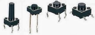
Here the switch is connected to the PORTB pin no 0 and 1, for Up and Down Counter. The value of the counter will decrease at the time it reaches to max value (i.e. 9). Till then switch 2 will not work. Only access to the switch for making counter in forward direction is allowed. When counter reaches to the 9, switch 1 will stop working and only switch 2 will come into action.


/*
 *
 *
 * Created: 17/10/13 3:24:24
 *  Author: Raj Prajapati.
 */


#include <avr/io.h> //Header file for AVR input/output.
#include <util/delay.h> //header file for delay.
char ssd[]={0x3f,0x06,0x5b,0x4f,0x66,0x6d,0x7d,0x07,0x7f,0x6f}; // Hexadecimal values for the 7 Segment display generated by the look up table
char i=-1;
int main(void)
{
char flag1=0,flag2=0,sw1=0,sw2=1; //flag for two switch.
DDRA=0XFF;
    while(1)
    {

if (bit_is_clear(PINB,0)&&flag1==0i&&i!=9&&sw1==0) //check switch 1 is Pressed.
{
++i;
PORTA=ssd[i];

Here the following uses the Switch to be connected on the PORTB, pin no 0 and 1, i.e PB0 and PB1.
PORTA is connected with the SEVEN SEGMENT display (common cathode). Switch used here is in Active Low condition.
Following is the Program to Interface two switch with SSD.


/*
 * DAY1QUE1.c
 *
 * Created: 10/15/13 17:00:24
 *  Author: Raj Prajapati
 */


#include <avr/io.h> //Header file for AVR input/output.
#include <util/delay.h> //header file for delay.
char ssd[]={0x3f,0x06,0x5b,0x4f,0x66,0x6d,0x7d,0x07,0x7f,0x6f}; // Hexadecimal values for the 7 Segment display generated by the look up table
char i=-1;
int main(void)
{
char flag1=0,flag2=0; //flag for two switch.
DDRA=0XFF;
    while(1)
    {

if (bit_is_clear(PINB,0)&&flag1==0i&&i!=9) //check switch 1 is Pressed.
{
++i;
PORTA=ssd[i];
flag1=1;
}
if (bit_is_set(PINB,0)) //Release condition for pressed switch 1.
{
flag1=0;
}
if (bit_is_clear(PINB,1)&&flag2==0&&i>0) //check switch 2 is pressed.
{
--i;
PORTA=ssd[i];
flag2=1;
}
if (bit_is_set(PINB,1)) //Release condition for pressed switch 1.
{
if (i<0&&flag2==1)

Wednesday, 16 October 2013


Here we had made use of 7 segment common cathode display for the Interfacing. Along with the Atmega16.
Simulation work is done in Proteus Software.
Header file: avr is providing its own header filr "avr/io.h"
                  for using delay in the avr , we had used util/delay.h
This header file can provide the delay in milli and micro seconds.


/*
 * DAY1QUE1.c
 *
 * Created: 10/15/13 17:00:24

 *  Author: Raj
 */


#include <avr/io.h>
#include <util/delay.h>

char ssd[]={0x3f,0x06,0x5b,0x4f,0x66,0x6d,0x7d,0x07,0x7f,0x6f}; // Hexadecimal values for the 7 Segment display generated by the look up table

int main(void)
{
char i=0;
DDRA=0XFF;
    while(1)
    {

Thursday, 5 September 2013

Advance LPG Gas Detector and Auto Booking System for Domestic and Commercial  Use (Electronics project)...


Advancement in the technologies have given us a safer and calm living of standard. Development in the different type of sensors that are easily available in market made the electronic research work more efficient, cheap and accurate.
                    LPG stands for Liquefied Petroleum Gas, scientifically well know as Butane or Propane (hydrocarbons), which is very highly combustible Gas. It is use as Fuel in Domestic field and in Industry fields also.
Basically LPG is use in Domestic field for cooking. There may occur hazard with such a Highly Combustible gas mostly due to leaking of this gas. If this leaked gas comes in contact with small part of fire also the it will become BOMB.
Here a advanced system is used where a Sensor Detect  leaking of LPG . This Sensor generates the Analog value which is then processed to the Microcontroller for further Processing.
In case of Gas leaking , exhaust fan will start automatically and will require manual reset so that all the leaked gas can be send outside the home and simultaneously Owner will receive the message of this miss-happening.

Saturday, 24 August 2013

INTERFACING LCD WITH ATMEGA16/32.....

Posted by Unknown On 18:11 | No comments

LCD INTERFACING WITH ATmega16 by RAJ PRAJAPATI


THIS IS THE CODE WRITTEN BY ME FOR THE 8 BIT MODE FOR LCD INTERFACING...


/*HEADER FILE TO USE LCD IN 8 BIT MODE
  PORTA FOR DATA PINS OF LCD
                                                PA0=DB0
                                                PA1=DB1
                                                PA2=DB2
                                                PA3=DB3
                                                PA4=DB4
                                                PA5=DB5
                                                PA6=DB6
                                                PA7=DB7
                PORTB
                                                PB0=RS
                                                PB1=RW
                                                PB2=RN
  DESIGNED BY:-                RAJ PRAJAPATI (NAGPUR INSTITUTE OF TECHNOLOGY, NAGPUR)
*/
/*---------------------------------------------------------------------------------------------------*/
                                                                //HEADER FILES
#include<avr/io.h>
#include<util/delay.h>
#include<stdlib.h>
/*----------------MACROS--------------------*/
#define rs 0
#define rw 1
#define en 2


Blogroll

Copyright © 2013 RAJ PRAJAPATI (raj@electronicsrj.com)

Comments

About Projects

We also Provide support in making Electronics Projects at different level at Cheapest price. Contact Us for the further help.