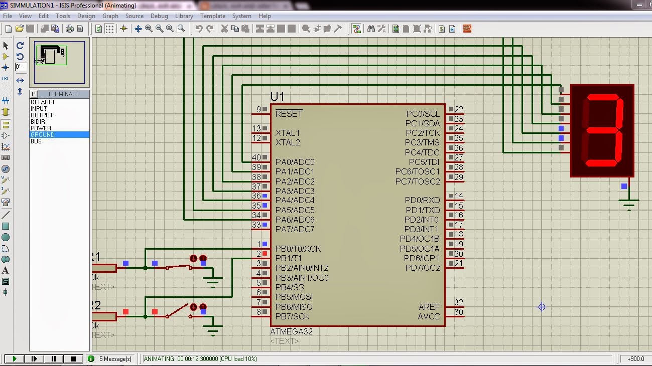
Here the following uses the Switch to be connected on the PORTB, pin no 0 and 1, i.e PB0 and PB1.
PORTA is connected with the SEVEN SEGMENT display (common cathode). Switch used here is in Active Low condition.
Following is the Program to Interface two switch with SSD.
/*
* DAY1QUE1.c
*
* Created: 10/15/13 17:00:24
* Author: Raj Prajapati
*/
#include <avr/io.h> //Header file for AVR input/output.
#include <util/delay.h> //header file for delay.
char ssd[]={0x3f,0x06,0x5b,0x4f,0x66,0x6d,0x7d,0x07,0x7f,0x6f}; // Hexadecimal values for the 7 Segment display generated by the look up table
char i=-1;
int main(void)
{
char flag1=0,flag2=0; //flag for two switch.
DDRA=0XFF;
while(1)
{
if (bit_is_clear(PINB,0)&&flag1==0i&&i!=9) //check switch 1 is Pressed.
{
++i;
PORTA=ssd[i];
flag1=1;
}
if (bit_is_set(PINB,0)) //Release condition for pressed switch 1.
{
flag1=0;
}
if (bit_is_clear(PINB,1)&&flag2==0&&i>0) //check switch 2 is pressed.
{
--i;
PORTA=ssd[i];
flag2=1;
}
if (bit_is_set(PINB,1)) //Release condition for pressed switch 1.
{
if (i<0&&flag2==1)
{
i=-1;
}
flag2=0;
}
}
}
AVR PROGRAMMING
Click here for AVR : Interfacing Seven Segment Dispay (Atmega16/32)


0 comments:
Post a Comment