Monday, 28 October 2013

AVR: Stopwatch With Interrupt Timer and Multiplexed 7 segment Display

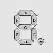
Here we are connecting the 7 segment display with PORTA, i.e. Multiplexing of six-7segment display, with the control lines to PORTB. Following is the program to Interface the 7segments.

Crystal : 8MHz
Time: 0.125uSec
Prescaler: clk/1025
Timer Interrupt : 25mSec.
For 1sec , run this timmer for 40 times.

We can achieve max delay of appx. 35000uSec or 35mSec with 8MHz crystal frequency and prescaler (clk/1024).

Program: 

/*
 * two_7seg.c
 *
 * Created: 27-Oct-13 19:08:04
 *  Author: avrnarm
 */ 

/* PROGRAM to execute the counter with the multiplexed 7 segent display */
#define FUSE_CKSEL0 0
#define FUSE_CKSEL1 0
#define FUSE_CKSEL2 1
#define FUSE_CKSEL3 0

#include<avr/io.h>
#define F_CPU 8000000Ul
#include<util/delay.h>
#include<avr/interrupt.h>

unsigned int j,ss=0,mm=0,hh=0;
char ssd[]={0x3f,0x06,0x5b,0x4f,0x66,0x6d,0x7d,0x07,0x7f,0x6f}; // Hexadecimal values for the 7 Segment display generated by the look up table
char ssd_dec[]={0xbf,0x86,0xdb,0xcf,0xE6,0xEd,0xFd,0x87,0xff,0xEf}; // Hexadecimal values for the 7 Segment display generated by the look up table

int main(void)
{
DDRA=0xFF;
DDRB=0xFF;
//*********************TIMER***(8MHz crystal....clk/1024 prescaler......Obtained 25ms delay
TCNT0=61;
TCCR0=0x05;
TIMSK=(1<<TOIE0);
//*********************
sei();
while(1)
    {
// for seconds
PORTB=0xFF;
PORTA=ssd[(ss)/10];

Friday, 25 October 2013

NotePad Design with Atmega16/32 on 16x2 LCD with UART


Here in this program we are designing the notepad by using Atmega16/32 as a controller and LCD for displaying the typed that we will be sending from the help of  UART. In Proteus, with the help of the Virtual Terminal , we will send the data to the uC and the same data will be displayed on the 16x2 LCD in the same way we type in the Notepad. Once you had written the max 32 character, Lcd will get clear and go back again to home position to provide you the space of the further character you will be sending from the UART.


Hardware Connection : -


***************************PROGRAM*****************************


//Program to interface the LCD, Uart and Keyboard

#include<avr/io.h>
#define F_CPU 1000000ul
#include<util/delay.h>
#include<stdlib.h>

//Flag to moniter no of bit received
char flag=0;


//Setting Fuse Bit

#define FUSE_CKSEL0 0
#define FUSE_CKSEL1 0
#define FUSE_CKSEL2 1
#define FUSE_CKSEL3 0

//**********************************LCD START************************************
/* LCD bit connection

Lcd Interfacing in 8-bit mode
PA0 --> D0
PA1 --> D1
PA2 --> D2
PA3 --> D3
PA4 --> D4
PA5 --> D5
PA6 --> D6
PA7 --> D7

PB0 --> RS
PB1 --> RW
PB2 --> EN

*/

//Macros For Lcd
#define LCD_PORT PORTA
#define rs (1<<0)
#define rw (1<<1)
#define en (1<<2)

KEYPAD...UART (Universal Asynchronous Receiver Transmitter)...AND LCD (Liquid crystal display) Interfacing with Atmaga16/32


Following code will be defining the processing of the UART (checked in Proteus) with baud rate of 1200 bits/second with internal crystal of the ATmega16.


Here we are connecting the Keypad in the PORTC of the uC , LCD on the PORTB and the Virtual terminal in the Proteus to summarize the  exact working of the Uart.

 We had connected 4x3 LCD Matrix. 


//Program to interface the LCD, Uart and Keyboard


#include<avr/io.h>

#define F_CPU 1000000ul
#include<util/delay.h>
#include<stdlib.h>

//Setting Fuse Bit


#define FUSE_CKSEL0 0

#define FUSE_CKSEL1 0
#define FUSE_CKSEL2 1
#define FUSE_CKSEL3 0


CONNECTION IN PROTEUS :


//**********************************LCD START************************************

/* LCD bit connection

Lcd Interfacing in 8-bit mode
PA0 --> D0
PA1 --> D1
PA2 --> D2
PA3 --> D3
PA4 --> D4
PA5 --> D5
PA6 --> D6
PA7 --> D7

PB0 --> RS
PB1 --> RW
PB2 --> EN

*/

//Macros For Lcd

#define LCD_PORT PORTA
#define rs (1<<0)
#define rw (1<<1)
#define en (1<<2)

//function Declaration

void init_lcd(void);
void cmd(unsigned char cmd_data);
void data(unsigned char l_data);
void enable(void);
void display(char *lcd_data);
void lcdgoto(unsigned char x,unsigned char y);
void display_value(long int x);
void lcd_clr(void);
//Function Definition for LCD
void init_lcd(void)
{
DDRA=0xFF;
DDRB=0xFF;

Thursday, 17 October 2013

Here the switch is connected to the PORTB pin no 0 and 1, for Up and Down Counter. The value of the counter will decrease at the time it reaches to max value (i.e. 9). Till then switch 2 will not work. Only access to the switch for making counter in forward direction is allowed. When counter reaches to the 9, switch 1 will stop working and only switch 2 will come into action.


/*
 *
 *
 * Created: 17/10/13 3:24:24
 *  Author: Raj Prajapati.
 */


#include <avr/io.h> //Header file for AVR input/output.
#include <util/delay.h> //header file for delay.
char ssd[]={0x3f,0x06,0x5b,0x4f,0x66,0x6d,0x7d,0x07,0x7f,0x6f}; // Hexadecimal values for the 7 Segment display generated by the look up table
char i=-1;
int main(void)
{
char flag1=0,flag2=0,sw1=0,sw2=1; //flag for two switch.
DDRA=0XFF;
    while(1)
    {

if (bit_is_clear(PINB,0)&&flag1==0i&&i!=9&&sw1==0) //check switch 1 is Pressed.
{
++i;
PORTA=ssd[i];

Here the following uses the Switch to be connected on the PORTB, pin no 0 and 1, i.e PB0 and PB1.
PORTA is connected with the SEVEN SEGMENT display (common cathode). Switch used here is in Active Low condition.
Following is the Program to Interface two switch with SSD.


/*
 * DAY1QUE1.c
 *
 * Created: 10/15/13 17:00:24
 *  Author: Raj Prajapati
 */


#include <avr/io.h> //Header file for AVR input/output.
#include <util/delay.h> //header file for delay.
char ssd[]={0x3f,0x06,0x5b,0x4f,0x66,0x6d,0x7d,0x07,0x7f,0x6f}; // Hexadecimal values for the 7 Segment display generated by the look up table
char i=-1;
int main(void)
{
char flag1=0,flag2=0; //flag for two switch.
DDRA=0XFF;
    while(1)
    {

if (bit_is_clear(PINB,0)&&flag1==0i&&i!=9) //check switch 1 is Pressed.
{
++i;
PORTA=ssd[i];
flag1=1;
}
if (bit_is_set(PINB,0)) //Release condition for pressed switch 1.
{
flag1=0;
}
if (bit_is_clear(PINB,1)&&flag2==0&&i>0) //check switch 2 is pressed.
{
--i;
PORTA=ssd[i];
flag2=1;
}
if (bit_is_set(PINB,1)) //Release condition for pressed switch 1.
{
if (i<0&&flag2==1)

Wednesday, 16 October 2013


Here we had made use of 7 segment common cathode display for the Interfacing. Along with the Atmega16.
Simulation work is done in Proteus Software.
Header file: avr is providing its own header filr "avr/io.h"
                  for using delay in the avr , we had used util/delay.h
This header file can provide the delay in milli and micro seconds.


/*
 * DAY1QUE1.c
 *
 * Created: 10/15/13 17:00:24

 *  Author: Raj
 */


#include <avr/io.h>
#include <util/delay.h>

char ssd[]={0x3f,0x06,0x5b,0x4f,0x66,0x6d,0x7d,0x07,0x7f,0x6f}; // Hexadecimal values for the 7 Segment display generated by the look up table

int main(void)
{
char i=0;
DDRA=0XFF;
    while(1)
    {

Sunday, 13 October 2013

Open file , Take input from KEYBOARD, write in the file, Display the content of the file and close the file.


/* Program to open the File, read data from the Keyboard and write it in the file.*/
/* User Progam , to be executed in the user space */
/* openfile3.c */
// Author : (Raj)

#include<stdio.h>
#include<fcntl.h>
static int count;
int main()
{
    int fd1,i,len;
    char buffwr[100],buffr[100];
    fd1=open("test1.txt",O_CREAT|O_RDWR,0777);    // Opening of file in read and write mode.
    if(fd1<0)
    {
        printf("File 1 cannot be open. \n");
        return 0;
    }
    else
    {
        printf("File Discripter value of the File 1 is : %d\n",fd1);
        printf("Enter the data to write into the file....\n");
        i=read(0,buffwr,100);
        buffwr[i]='\0';
        len=strlen(buffwr);
        write(fd1,buffwr,len);

LINUX : Opening and Closing the File.

Posted by Unknown On 21:47 | No comments


Program to Open a File and Close it , Along with printing the File Discripter value.

Program will never return the file discripter value as 0,1,or 2 as these values are already reserved for 
0---> Standard Input
1---> Standard Output
2---> Standard Output

Here two system calls are used, read and write, you can get the details of it just by typing man read or man write in the terminal window.

Save the file in .c extension, compile by GCC compiler and execute it.

*************************
/* Program to open the File and Print its file discripter value */
/* User Progam , to be executed in the user space */
/* openfile1.c */

#include<stdio.h>
#include<fcntl.h>

int main()
{
    int fd1,fd2;
    fd1=open("test1.txt",O_CREAT|O_RDWR,0777);
    fd2=open("test2.txt",O_CREAT|O_RDWR,0777);
    if(fd1<0)
    {
        printf("File 1 cannot be open. \n");
    }
    else
    {
        printf("File Discripter value of the File 1 is : %d",fd1);
    }

Thursday, 10 October 2013

Basic program to make the module in Kernel Space and add it into the process

Write the program with the file extension ".c" . After that, make the Makefile. Then execute the Makefile by writing make. after that insert the module in the Process by writing insmod <filename>.ko . Then check the Kernel module by writing the command dmesg|less. For removing the module from the Process write rmmod <filename>.ko.

//basic.c
#include<linux/init.h>
#include<linux/module.h>
MODULE_LICENSE("GPL");
MODULE_AUTHOR("RAJ");

static int hello_init(void)
{
printk(KERN_ALERT "HELLO , THERE \n");
return 0;

}


static int hello_exit(void)
{
printk(KERN_ALERT "Goodbye everyone i m gonna find u and kill you \n");
return 0;
}

module_init(hello_init);
module_exit(hello_exit);


Tutorial :

Program in a KERNEL to be use by user for open,close,read and write, along with the USER program to access Kernel program, with make file.

-----------------------------------------------------------------------------------------------------

/* Program to make a kernel to be accessed by the user */
#include<linux/module.h>
#include<linux/kernel.h>
#include<linux/kdev_t.h>
#include<linux/fs.h>
#include<linux/cdev.h>
#include<asm/uaccess.h>
MODULE_LICENSE("GPL");
struct cdev rss_str;
int major=0;
int minor=0;
dev_t rss;
void rss_reg();
static int rss_init()
{
printk("intializing module\n");
rss_reg();
return 0; }
static void rss_release()
{
printk("Exiting module\n");
cdev_del(&rss_str);
unregister_chrdev_region(rss,1);
}
// READ file

Blogroll

Copyright © 2013 RAJ PRAJAPATI (raj@electronicsrj.com)

Comments

About Projects

We also Provide support in making Electronics Projects at different level at Cheapest price. Contact Us for the further help.